회전 변환 행렬 (2D, 3D)
2020, Jan 02
- 참조 : https://en.wikipedia.org/wiki/Rotation_matrix
- 참조 : https://ko.wikipedia.org/wiki/회전변환행렬
- 이번 글에서는 2D와 3D 상태에서의 좌표의 회전 변환하는 방법에 대하여 알아보도록 하겠습니다.
- 다른 방식의 회전 변환 개념은 아래 링크에서 확인하실 수 있습니다. 다음 내용은 본 글에서 다루는
euler rotation의 단점을 개선한 내용입니다.
목차
-
2D에서의 회전 변환
-
회전 변환 행렬 유도
-
임의의 점을 중심으로 회전 변환
-
3D에서의 회전 변환
-
회전 변환 행렬의 구성 요소
-
회전 변환 행렬의 직교성
-
Roll, Pitch, Yaw와 Rotation 행렬의 변환
2D에서의 회전 변환
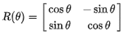
- 2D 좌표계에서 회전 변환을 할 때 사용하는 변환 행렬은 다음과 같습니다.
- \[R(\theta) = \begin{bmatrix} \text{cos}\theta & -\text{sin}\theta \\ \text{sin}\theta & \text{cos}\theta \end{bmatrix}\]
- 여기서 \(\theta\)는 각도에 해당합니다. 반시계 방향으로 회전하는 방향이 + 각도가 됩니다.
- 위 회전 행렬을 이용하여 \((x, y)\) 좌표를 회전 변환을 하면 다음과 같습니다.
- \[\begin{bmatrix} \text{cos}\theta & -\text{sin}\theta \\ \text{sin}\theta & \text{cos}\theta \end{bmatrix} \begin{bmatrix} x \\ y \end{bmatrix} = \begin{bmatrix} x \text{cos}\theta - y \text{sin}\theta \\ x \text{sin}\theta + y \text{cos}\theta \end{bmatrix} = \begin{bmatrix} x' \\ y' \end{bmatrix}\]
- 위 식을 이용하여 회전 변환한 좌표를 구하면 다음과 같습니다.
- 자주 사용하는 회전인 90도 회전 / 180도 회전 / 270도 회전은 다음과 같습니다.
- \[R(\frac{\pi}{2}) = \begin{bmatrix} 0 & -1 \\ 1 & 0 \end{bmatrix}\]
- \[R(\frac{\pi}{2}) = \begin{bmatrix} -1 & 0 \\ 0 & -1 \end{bmatrix}\]
- \[R(\frac{3\pi}{2}) = \begin{bmatrix} 0 & 1 \\ -1 & 0 \end{bmatrix}\]
회전 변환 행렬 유도
- 회전 변환을 다루는 방법에 대해서는 위 글에서 다루었습니다. 그러면 왜 저런 형태의 행렬식이 유도되었는 지에 대하여 다루어 보겠습니다.
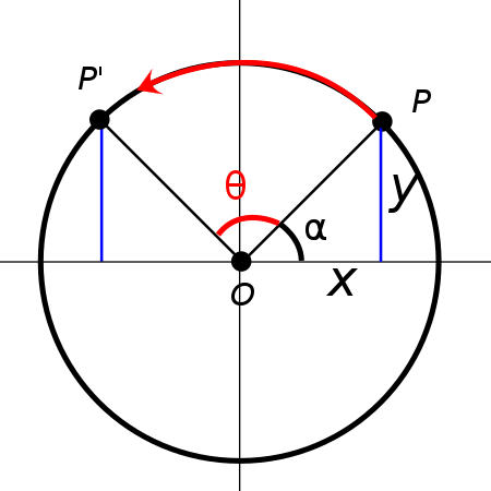
- 먼저 앞에서 다룬 회전 변환은 원점을 기준으로 회전을 하게 됩니다. 따라서 위 그림에서도 원점을 중심으로
P가P'로 어떻게 변환되는 지 다루어 보도록 하겠습니다. - 아래 식에서 \(P, \overline{OP}, \text{cos}(\alpha), \text{sin}(\alpha)\)를 정의해 보겠습니다.
- \[P = (x, y)\]
- \[\overline{OP} = l = \sqrt{(x - 0)^{2} + (y - 0)^{2})} = \sqrt{x^{2} + y^{2}}\]
- \[\text{cos}(\alpha) = \frac{x}{\overline{OP}} = \frac{x}{\sqrt{x^{2} + y^{2}}}\]
- \[\text{sin}(\alpha) = \frac{y}{\overline{OP}} = \frac{y}{\sqrt{x^{2} + y^{2}}}\]
- 위 식을 그대로 이용하여 \(P'\)에 적용해 보도록 하겠습니다. \(P' = (x', y')\)는 \(P = (x, y)\)를 \(+\theta\) 만큼 회전 시킨 것이므로 회전 각도 만큼 반영해여 식을 적어보겠습니다.
- \[x' = \sqrt{x^{2} + y^{2}} \text{cos}(\alpha + \theta)\]
- \[y' = \sqrt{x^{2} + y^{2}} \text{sin}(\alpha + \theta)\]
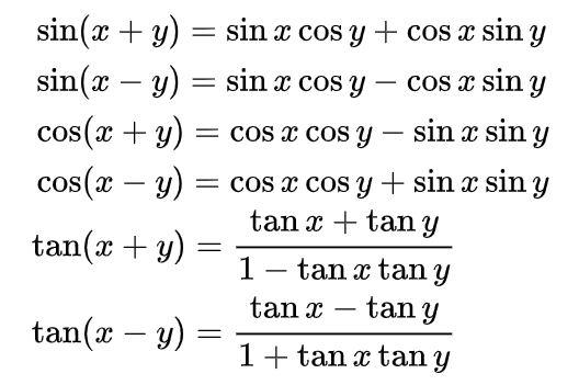
- 삼각함수의 덧셈 정리를 이용하여 식을 풀어보도록 하겠습니다.
- \[x' = \sqrt{x^{2} + y^{2}}(\text{cos}(\alpha)\text{cos}(\theta) -\text{sin}(\alpha)\text{sin}(\theta)) = \Biggl(\sqrt{x^{2} + y^{2}}\frac{x}{\sqrt{x^{2} + y^{2}}}\text{cos}(\theta) - \sqrt{x^{2} + y^{2}}\frac{y}{\sqrt{x^{2} + y^{2}}}\text{sin}(\theta) \Biggr) = x\text{cos}(\theta) - y\text{sin}(\theta)\]
- \[y' = \sqrt{x^{2} + y^{2}}\text{sin}(\alpha + \theta) = \sqrt{x^{2} + y^{2}}(\text{sin}(\alpha)\text{cos}(\theta) + \text{cos}(\alpha)\text{sin}(\theta)) = \Biggl(\sqrt{x^{2} + y^{2}}\frac{y}{\sqrt{x^{2} + y^{2}}}\text{cos}(\theta) + \sqrt{x^{2} + y^{2}}\frac{x}{\sqrt{x^{2} + y^{2}}}\text{sin}(\theta) \Biggr) = y\text{cos}(\theta) + x\text{sin}(\theta)\]
- 위에서 유도한 식을 정리하면 다음과 같습니다.
- \[\begin{pmatrix} x' \\ y' \end{pmatrix} = \begin{pmatrix} \text{cos}\theta & -\text{sin}\theta \\ \text{sin}\theta & \text{cos}\theta \end{pmatrix} \begin{pmatrix} x \\ y \end{pmatrix}\]
임의의 점을 중심으로 회전 변환
- 앞에서 다룬 내용은 모두
원점을 기준으로 회전한 것입니다. 좀 더 일반적인 케이스를 적용하기 위해 기준이 원점이 아니라 특정 좌표를 기준으로 회전 시켜보도록 하겠습니다.
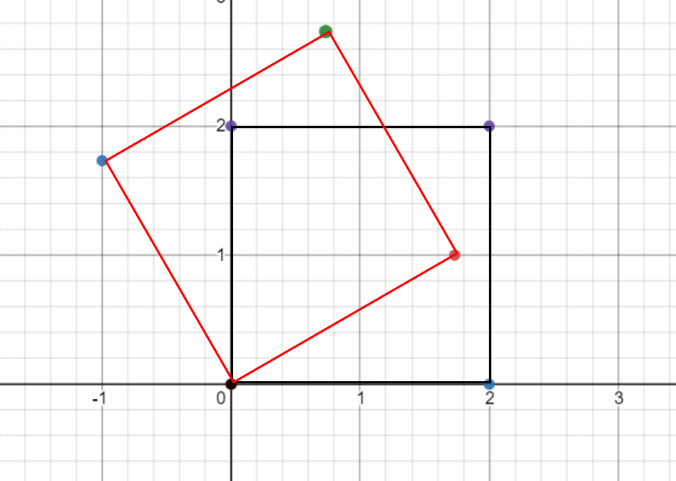
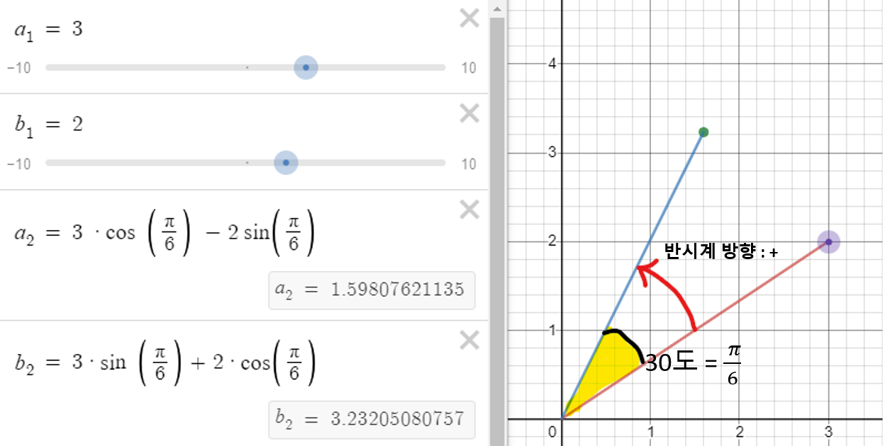
- 위 그림을 보면 원점을 기준으로 30도 회전한 것을 알 수 있습니다.
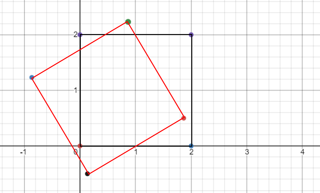
- 반면에 위 그림에서는 회전한 기준을 보면 (1, 0)임을 알 수 있습니다.
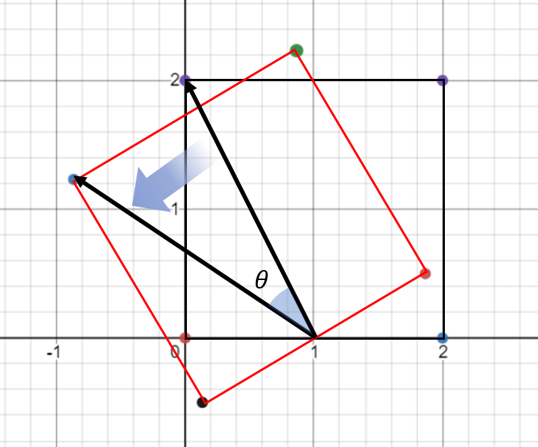
- 지금부터 해야할 작업은 위 그림 처럼 기준점에서 각 점 방향으로의 벡터를 회전하는 것입니다. (물론 반시계 방향 회전이 + 회전 각도 입니다.)
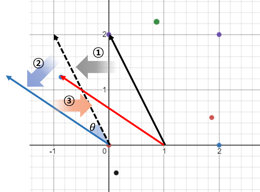
- ① 기준점을 \(v_{0} = (x_{base}, y_{base})\) 이라고 하면 각 점 방향으로의 벡터는 \(v_{i} - v_{0} = (x_{i} - x_{base}, y_{i} - y_{base})\)이 됩니다.
- ② 이 벡터를 앞에서 알아본 변환 행렬을 이용하여 회전 시키면 됩니다.
- \[\begin{pmatrix} x' \\ y' \end{pmatrix} = \begin{pmatrix} \text{cos}\theta & -\text{sin}\theta \\ \text{sin}\theta & \text{cos}\theta \end{pmatrix} \begin{pmatrix} x - x_{base} \\ y - y_{base} \end{pmatrix}\]
- 여기 까지 계산 하면 (\((0, 0)\) → \((x - x_{base}, y - y_{base})\)) 방향과 크기의 벡터가 \(\theta\) 만큼 회전하여 \((x', y')\)가 되었습니다.
- ③ 벡터의 시작점을 회전 기준인 \((x_{base}, y_{base})\)으로 옮겨줍니다.
- ①, ②, ③ 과정을 식으로 옮기면 다음과 같습니다.
- \[\begin{pmatrix} x' \\ y' \end{pmatrix} = \begin{pmatrix} \text{cos}\theta & -\text{sin}\theta \\ \text{sin}\theta & \text{cos}\theta \end{pmatrix} \begin{pmatrix} x - x_{base} \\ y - y_{base} \end{pmatrix} + \begin{pmatrix} x_{base} \\ y_{base} \end{pmatrix}\]
3D에서의 회전 변환
- 3D에서의 회전 변환은 2차원에서 사용한 회전 변환 행렬을 유사하게 사용합니다. 다만 이 때, 3차원에 맞춰서 행렬의 차원이 늘어나게 되고 각 차원별로 회전을 고려해 주어야 합니다.
- 예를 들어서 \(R_{x}(\theta)\)는 x축을 중심으로 회전하는 행렬 변환이고 \(R_{y}(\theta)\)는 y축을 중심으로 \(R_{z}(\theta)\)는 z축을 중심으로 회전하는 행렬 변환입니다.
- \[R_{x}(\theta) = \begin{bmatrix} 1 & 0 & 0 \\ 0 & \text{cos}\theta & -\text{sin}\theta \\ 0 & \text{sin}\theta & \text{cos}\theta \end{bmatrix}\]
- \[R_{y}(\theta) = \begin{bmatrix} \text{cos}\theta & 0 & \text{sin}\theta \\ 0 & 1 & 0 \\ -\text{sin}\theta & 0 & \text{cos}\theta \end{bmatrix}\]
- \[R_{z}(\theta) = \begin{bmatrix} \text{cos}\theta & -\text{sin}\theta & 0 \\ \text{sin}\theta & \text{cos}\theta & 0 \\ 0 & 0 & 1 \end{bmatrix}\]
- 이 행렬을 정리해 보려고 하는데, 그 전에
roll,yaw,pitch에 대하여 알아보겠습니다.
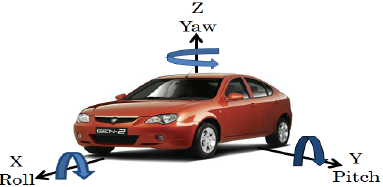
- 위 회전축 기준으로
roll은 x축을 기준으로 회전한 양을 뜻하고pitch는 y축을 기준으로 회전한 양 그리고yaw는 z축을 기준으로 회전한 양을 뜻합니다. 위 그림처럼 생각하시면 됩니다.- 예를 들어 자동차가 좌회전 또는 우회전을 한다면 z축을 기준으로 회전을 하는 것이므로
yaw의 변화가 있게 됩니다.
- 예를 들어 자동차가 좌회전 또는 우회전을 한다면 z축을 기준으로 회전을 하는 것이므로
- 그러면 \(R_{x}(\theta)\), \(R_{y}(\theta)\) 그리고 \(R_{z}(\theta)\) 각각 x축, y축, z축을 기준으로 회전하는 회전 변환 행렬이 됩니다.
- x축을 기준으로 회전한
roll angle을 \(\alpha\), y축을 기준으로 회전한pitch angle을 \(\beta\) 마지막으로 z축을 기준으로 회전한yaw angle을 \(\gamma\)로 두겠습니다.
- \[R = R_{z}(\gamma)R_{y}(\beta)R_{x}(\alpha) = \begin{bmatrix} \text{cos}\gamma & -\text{sin}\gamma & 0 \\ \text{sin}\gamma & \text{cos}\gamma & 0 \\ 0 & 0 & 1 \end{bmatrix} \begin{bmatrix} \text{cos}\beta & 0 & \text{sin}\beta \\ 0 & 1 & 0 \\ -\text{sin}\beta & 0 & \text{cos}\beta \end{bmatrix} \begin{bmatrix} 1 & 0 & 0 \\ 0 & \text{cos}\alpha & -\text{sin}\alpha \\ 0 & \text{sin}\alpha & \text{cos}\alpha \end{bmatrix}\]
- 위 변환 행렬을 모두 곱하면 roll, pitch, yaw angle을 모두 고려한 회전을 나타낼 수 있습니다.
- 위 식을 풀어서 나타내면 다음과 같습니다.
- \[R = \begin{bmatrix} \text{cos}\gamma \ \text{cos}\beta & \text{cos}\gamma \ \text{sin}\beta \ \text{sin}\alpha - \text{sin}\gamma \ \text{cos}\alpha & \text{cos}\gamma \ \text{sin}\beta \ \text{cos}\alpha + \text{sin}\gamma \ \text{sin}\alpha \\ \text{sin}\gamma \ \text{cos}\beta & \text{sin}\gamma \ \text{sin}\beta \ \text{sin}\alpha + \text{cos}\gamma \ \text{cos}\alpha & \text{sin}\gamma \ \text{sin}\beta \ \text{cos}\alpha - \text{cos}\gamma \ \text{sin}\alpha \\ -\text{sin}\beta & \text{cos}\beta \ \text{sin} \alpha & \text{cos}\beta \ \text{cos} \alpha \\ \end{bmatrix}\]
- 위 식을 파이썬 코드로 나타내면 다음과 같습니다.
import numpy as np

def euler_to_rotation_matrix(roll, pitch, yaw):
    # Convert angles to radians
    roll = np.radians(roll)
    pitch = np.radians(pitch)
    yaw = np.radians(yaw)

    # Define individual rotation matrices
    Rx = np.array([[1, 0, 0],
                   [0, np.cos(roll), -np.sin(roll)],
                   [0, np.sin(roll), np.cos(roll)]])

    Ry = np.array([[np.cos(pitch), 0, np.sin(pitch)],
                   [0, 1, 0],
                   [-np.sin(pitch), 0, np.cos(pitch)]])

    Rz = np.array([[np.cos(yaw), -np.sin(yaw), 0],
                   [np.sin(yaw), np.cos(yaw), 0],
                   [0, 0, 1]])

    # Combine the rotations
    R = np.dot(Rz, np.dot(Ry, Rx))
    return R
회전 변환 행렬의 구성 요소
- 회전 변환 행렬의 경우 각 열의 성분이 각 축의
기저 벡터 (basis vector)가 회전 되었을 때의 벡터를 의미합니다. 3차원 행렬의 경우 \(X, Y, Z\) 순서로 축의 의미를 가진다면 회전 변환 행렬의 첫번째 열은 \(X\) 축의 기저 벡터를 회전 변환하였을 때의 벡터, 두번째 열은 \(Y\) 축의 기저 벡터를 회전 변환하였을 때의 벡터, 세번째 열은 \(Z\) 축의 기저 벡터를 회전 변환하였을 때의 벡터를 의미합니다. - 각 축의 기저 벡터를 회전하는 예시를 확인하면 그 뜻을 쉽게 알 수 있습니다.
- \[\begin{bmatrix} R_{11} & R_{12} & R_{13} \\ R_{21} & R_{22} & R_{23} \\ R_{31} & R_{32} & R_{33} \end{bmatrix} \begin{bmatrix} 1 \\ 0 \\ 0 \end{bmatrix} = \begin{bmatrix} R_{11} \\ R_{21} \\ R_{31} \end{bmatrix}\]
- \[\begin{bmatrix} R_{11} & R_{12} & R_{13} \\ R_{21} & R_{22} & R_{23} \\ R_{31} & R_{32} & R_{33} \end{bmatrix} \begin{bmatrix} 0 \\ 1 \\ 0 \end{bmatrix} = \begin{bmatrix} R_{12} \\ R_{22} \\ R_{32} \end{bmatrix}\]
- \[\begin{bmatrix} R_{11} & R_{12} & R_{13} \\ R_{21} & R_{22} & R_{23} \\ R_{31} & R_{32} & R_{33} \end{bmatrix} \begin{bmatrix} 0 \\ 0 \\ 1 \end{bmatrix} = \begin{bmatrix} R_{13} \\ R_{23} \\ R_{33} \end{bmatrix}\]
- 첫번째 예시인 \(X\) 축의 예시를 살펴보면 기저 벡터가 \([1, 0, 0]^{T} \to [R_{11}, R_{21}, R_{31}]^{T}\) 로 변환된 것을 알 수 있습니다. 두번째, 세번째 예시를 통하여 \(Y, Z\) 축이 어떻게 변하는 지 또한 확인할 수 있습니다.
- 다음 예시를 통하여 간단하게 회전 변환의 역할에 대하여 알아보도록 하겠습니다.
- \[\begin{bmatrix} 0 & -1 & 0 \\ 0 & 0 & -1 \\ 1 & 0 & 0 \end{bmatrix}\]
- 먼저 첫번째 열인 \([0, 0, 1]^{T}\) 을 통해 \(X\) 축의 기저 벡터에 회전 변환 행렬을 적용하면 \([1, 0, 0] \to [0, 0, 1]^{T}\) 이 된 것을 알 수 있습니다. 즉, \(Z\) 축의 기저 벡터 처럼 변경 되었습니다.
- 두번째 열인 \([-1, 0, 0]^{T}\) 을 통해 \(Y\) 축의 기저 벡터에 회전 변환 행렬을 적용하면 \([0, 1, 0] \to [-1, 0, 0]^{T}\) 이 된 것을 알 수 있습니다. 즉, 음의 방향의 \(X\) 축 기저 벡터 처럼 변경 되었습니다.
- 세번째 열인 \([0, -1, 0]^{T}\) 을 통해 \(Z\) 축의 기저 벡터에 회전 변환 행렬을 적용하면 \([0, 0, 1] \to [0, -1, 0]^{T}\) 이 된 것을 알 수 있습니다. 즉, 음의 방향의 \(Y\) 축 기저 벡터 처럼 변경 되었습니다.
- 따라서
R[:, 0],R[:, 1],R[:, 2]성분을 이용하면 기저 벡터가 어떻게 회전 변환 되는 지 알 수 있습니다.
- 임의의 회전 행렬을 적용하였을 때, 현재 좌표축 기준으로 변환된 좌표축에서의 기저 벡터를 구하고 싶다면 각 열에서 절대값이 가장 큰 축을 기저 벡터로 간주하여 기저 벡터를 구성하면 됩니다. 이 때, 부호 또한 반영하면 현재 기저 벡터 기준으로 축의 방향 또한 고려하여 확인할 수 있습니다.
R = np.array([
    0.00463, -0.99998, 0.00385,
    -0.01405, -0.00391, -0.99989,
    0.99989, 0.00457, -0.01407]
).reshape(3, 3)

basis_rotation = np.zeros((3, 3), dtype=np.float32)
for i in range(3):
    axis = np.argmax(np.abs(R[:, i]))
    if R[axis, i] > 0:
        basis_rotation[axis, i] = 1.0
    elif R[axis, i] < 0:
        basis_rotation[axis, i] = -1.0
    else:
        basis_rotation[axis, i] = 0.0

print(basis_rotation)
# [[ 0. -1.  0.]
#  [ 0.  0. -1.]
#  [ 1.  0.  0.]]
basis_rotation이 앞에서 해석한 내용과 동일한 값을 가집니다. 이와 같은 방법으로 현재 좌표계 기준의 기저 벡터가 회전 변환을 거쳤을 때, 어떻게 바뀌는 지 확인할 수 있습니다.
회전 변환 행렬의 직교성
- 지금까지 살펴본
rotation행렬은orthogonal행렬이며 다음과 같은 성질을 따릅니다.
- \[R^{T} = R^{-1}\]
- \[R^{T} R = I\]
orthogonal또는orthonormal인 행렬 \(Q\) 가 있을 때, \(QQ^{T} = Q^{T}Q = I\) 임은 필요충분 조건임이 알려져 있습니다.- 앞에서 살펴본
2D,3D회전 변환 행렬의 경우도 \(RR^{T} = R^{T}R = I\) 를 만족하며 일반적으로orthogonal형태이므로orthogonal하다고 말할 수 있습니다. - 또한
orthogonal한 경우 determinant가 1을 만족하는데 이 조건에도 만족하게 됩니다.
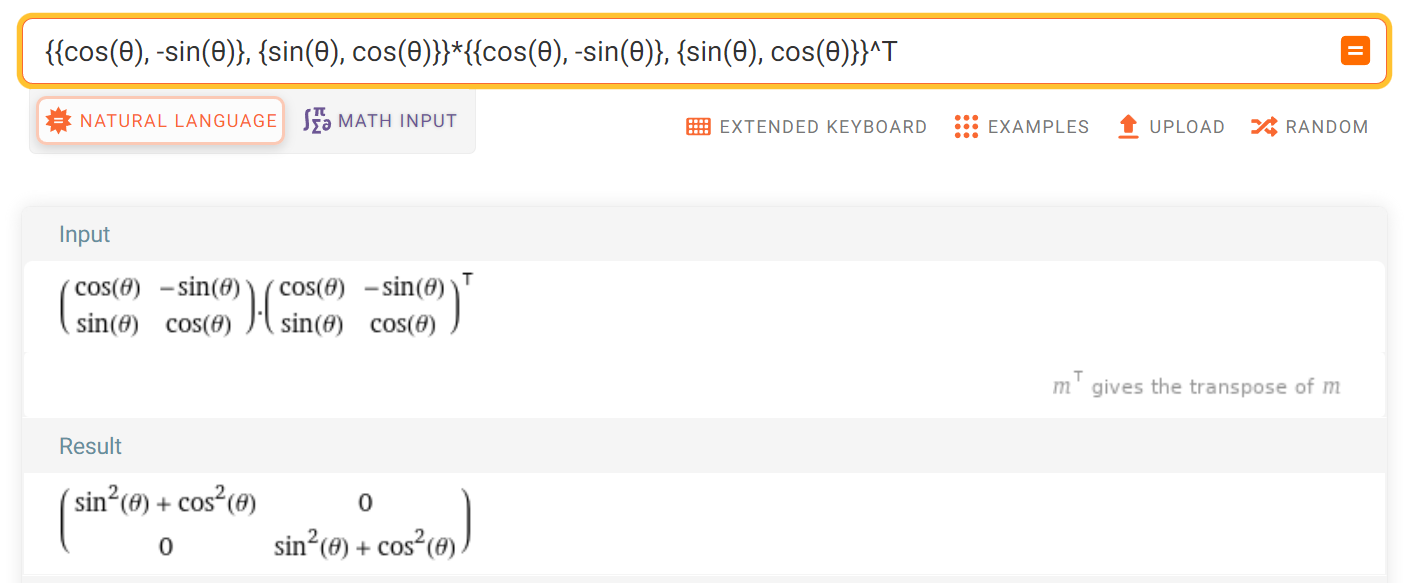
- 위 계산 결과와 같이 2D 회전 변환 행렬 \(R\) 의 \(RR^{T} = I\) 임을 확인할 수 있습니다.
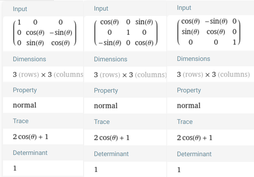
- 3D 회전 변환 행렬의 경우 간단히
det(R) = I임을 통해orthogonal임을 확인해 보겠습니다. -
아래 식과 같이
- \[R = R_z(\alpha)\,R_y(\beta)\,R_x(\gamma)\]
- \[R^T\,R=(R_z\,R_y\,R_x)^T\,(R_z\,R_y\,R_x)=R_x^T\,R_y^T\,R_z^T\,R_z\,R_y\,R_x\]
- \[R_{x}^{T}R_{X} = I\]
- \[R_{y}^{T}R_{y} = I\]
- \[R_{z}^{T}R_{z} = I\]
- \[\therefore R^{T}R = I\]
- \[\text{plus, } \det(R)=\det(R_z)\,\det(R_y)\,\det(R_x)=1\times 1\times 1=1\]
- 아래와 같이 3D 회전 변환 행렬의 각 방향의 \(R_{x}, R_{y}, R_{z}\) 의 determinant는 1임을 확인할 수 있습니다.
Roll, Pitch, Yaw와 Rotation 행렬의 변환
- 참조 : https://eecs.qmul.ac.uk/~gslabaugh/publications/euler.pdf
- 참조 : atan과 atan2 비교
- 지금까지 살펴본 방식은
Roll,Pitch,Yaw를 이용하여Rotation행렬을 구하는 방법에 대하여 살펴보았습니다. - 이번에는 임의의
Rotation행렬이 주어졌을 때, 이 행렬을Roll,Pitch,Yaw로 분해하는 방법을 알아보도록 하겠습니다. 3차원 좌표축의 기준은 앞에서 다룬바와 같이 \(X\) 축이 전방, \(Y\) 축이 왼쪽, \(Z\) 축이 위로 향하는Forward-Left-Up순서의 좌표축을 의미합니다. 만약 다른 좌표축 기준에서Roll,Pitch,Yaw성분을 분해하려면 아래 내용을 이해한 다음에 분해 순서 및 방식을 일부 수정하여 적용해야 합니다.
- 앞에서
Roll,Pitch,Yaw각각은 다음과 같은 형태로 표현할 수 있었습니다. 아래 식에서 \(\psi\) 는 \(x\) 축의 회전인Roll의 각도를 의미하며 \(\theta\) 는 \(y\) 축의 회전인Pitch의 각도를 의미하고 마지막으로 \(\phi\) 는 \(z\) 축의 회전인Yaw의 각도를 의미합니다.
- \[R_{x}(\psi) = \begin{bmatrix} 1 & 0 & 0 \\ 0 & \cos{\psi} & -\sin{\psi} \\ 0 & \sin{\psi} & \cos{\psi} \end{bmatrix}\]
- \[R_{y}(\theta) = \begin{bmatrix} \cos{\theta} & 0 & \sin{\theta} \\ 0 & 1 & 0 \\ -\sin{\theta} & 0 & \cos{\theta} \end{bmatrix}\]
- \[R_{z}(\phi) = \begin{bmatrix} \cos{\phi} & -\sin{\phi} & 0 \\ \sin{\phi} & \cos{\phi} & 0 \\ 0 & 0 & 1 \end{bmatrix}\]
-
앞에서 다룬 바와 같이
Rotation행렬은 다음과 같이Roll,Pitch,Yaw를 이용하여 표현할 수 있었습니다. 회전 순서는 \(R_{x}, R_{y}, R_{z}\) 순서로 곱해지기 때문에Roll,Pitch,Yaw순서로 회전 됩니다. - \[\begin{align} R &= R_{z}(\phi)R_{y}(\theta)R_{x}(\psi) \\ &= \begin{bmatrix} \cos{\theta}\cos{\phi} & \sin{\psi}\sin{\theta}\cos{\phi}-\cos{\psi}\sin{\phi} & \cos{\psi}\sin{\theta}\cos{\phi} + \sin{\psi}\sin{\phi} \\ \cos{\theta}\sin{\phi} & \sin{\psi}\sin{\theta}\sin{\phi} + \cos{\psi}\cos{\phi} & \cos{\psi}\sin{\theta}\sin{\phi}-\sin{\psi}\cos{\phi} \\ -\sin{\theta} & \sin{\psi}\cos{\theta} & \cos{\psi}\cos{\theta} \end{bmatrix} \\ &= \begin{bmatrix} R_{11} & R_{12} & R_{13} \\ R_{21} & R_{22} & R_{23} \\ R_{31} & R_{32} & R_{33}\end{bmatrix} \end{align}\]
- 현재 알고 싶은 정보는 위
Rotation행렬 \(R\) 을 이용하여 \(\psi, \theta, \phi\) 를 구하고 싶은 것입니다.
-
2개의 \(\theta\) 구하기
- 앞에서 \(R\) 을 구하였을 때, \(R_{31}\) 은 다음과 같습니다.
- \[R_{31} = -\sin{(\theta)}\]
- 따라서 \(\theta\) 를 쉽게 구할 수 있습니다.
- \[\theta = \sin^{-1}{(-R_{31})} = -\sin^{-1}{(R_{31})}\]
- 추가적으로 \(\sin{(\pi - \theta)} = \sin{\theta}\) 를 만족하므로 다음과 같이 2개의 식을 만족하는 \(\theta\) 를 구할 수 있습니다. 단, \(R_{31} \ne \pm 1\) 인 경우를 가정하며 이유는 글의 뒷부분에서 이어서 설명하도록 하겠습니다.
- \[\theta_{1} = -\sin^{-1}{(R_{31})}\]
- \[\theta_{2} = \pi - \theta_{1} = \pi + \sin^{-1}{(R_{31})}\]
- 위 식의 전개와 같이 \(\theta\) 가 2 종류가 나오기 때문에 최종 해 또한 2 종류로 도출됩니다.
-
대응되는 \(\psi\) 구하기
- 위 식에서 \(R_{32}, R_{33}\) 을 이용하면 \(\psi\) 를 구할 수 있습니다.
- \[\frac{R_{32}}{R_{33}} = \frac{\sin{(\psi)}\cos{(\theta)}}{\cos{(\psi)}\cos{(\theta)}} = \frac{\sin{(\psi)}}{\cos{(\psi)}} = \tan{(\psi)}\]
- \[\psi = \text{atan2}(R_{32}, R_{33})\]
- 위 식의 \(\text{atan2}\) 는 수치적 안정성을 위해 사용합니다. 일반적인 \(\text{atan}\) 은 1사분면과 4사분면만 표현할 수 있습니다. 즉, 분자, 분모가 모두 양수이거나 모두 음수인 경우만 \(\text{atan}\) 을 연산할 수 있습니다. 반면에 4개의 사분면에서 모두 \(\text{atan}\) 을 적용하기 위해 함수화한 것이 \(\text{atan2}\) 라고 말할 수 있습니다. 상세 내용은 아래 링크를 참조하시기 바랍니다.
- 참조 : atan과 atan2 비교
- 따라서 \(\text{atan2}\) 를 적용할 때에는 부호를 잘 고려해서 함수에 적용하면 위 링크에서 예외 처리한 내용을 고민하지 않고 계산할 수 있습니다.
- 따라서 앞선 식 \(\frac{R_{32}}{R_{33}} = \frac{\sin{(\psi)}\cos{(\theta)}}{\cos{(\psi)}\cos{(\theta)}} = \frac{\sin{(\psi)}}{\cos{(\psi)}}\) 에서 단순히 \(\cos{(\theta)}\) 를 소거하지 않고 다음과 같이 연산해 줍니다. 다음과 같이 연산하면 \(\cos{(\theta)} \ne 0\) 일 때에 연산이 모두 유효합니다.
- \[\psi = \text{atan2}(\frac{R_{32}}{\cos{(\theta)}}, \frac{R_{33}}{\cos{(\theta)}})\]
- 위 식에서 \(\cos{(\theta)}\) 는 \(\theta\) 의 값이 1, 4 사분면에 있으면 양수이고 2, 3 사분면에 있으면 음수이기 때문에 위 식과 같이 부호를 고려한다면 \(\theta\) 의 값에 따라 \(\psi\) 를 구할 수 있습니다.
- 앞선 식에서 \(\theta\) 의 후보로 \(\theta_{1}, \theta_{2}\) 가 있었기 때문에 다음과 같이 2개의 \(\psi_{1}, \psi_{2}\) 를 구할 수 있습니다. \(\cos{(\theta)} = 0\) 인 경우는 글 뒷부분에서 한번에 예외처리 하도록 하겠습니다.
- \[\psi_{1} = \text{atan2}(\frac{R_{32}}{\cos{(\theta_{1})}}, \frac{R_{33}}{\cos{(\theta_{1})}})\]
- \[\psi_{2} = \text{atan2}(\frac{R_{32}}{\cos{(\theta_{2})}}, \frac{R_{33}}{\cos{(\theta_{2})}})\]
-
대응되는 \(\phi\) 구하기
- 앞에서 \(\psi_{1}, \psi_{2}\) 를 구할 때에는 \(R_{32}, R_{33}\) 을 이용하였습니다. \(\phi\) 를 구할 때에는 \(R_{21}, R_{11}\) 을 이용해 보도록 하겠습니다. 방식은 완전히 동일합니다.
- \[\phi = \text{atan2}(\frac{R_{21}}{\cos{(\theta)}}, \frac{R_{11}}{\cos{(\theta)}})\]
- 이 경우에도 \(\cos{(\theta)} \ne 0\) 일 때, 계산이 모두 유효하며 아래와 같이 2개의 \(\phi_{1}, \phi_{2}\) 를 구할 수 있습니다.
- \[\phi_{1} = \text{atan2}(\frac{R_{21}}{\cos{(\theta_{1})}}, \frac{R_{11}}{\cos{(\theta_{1})}})\]
- \[\phi_{2} = \text{atan2}(\frac{R_{21}}{\cos{(\theta_{2})}}, \frac{R_{11}}{\cos{(\theta_{2})}})\]
-
\(\cos{(\theta)} \ne 0\) 일 때의 Euler Angles
- 지금까지 살펴본 방법으로 \(\cos{(\theta)} \ne 0\) 일 때, 다음과 같이 2가지
Euler Angles를 구할 수 있습니다.
- \[(\psi_{1}, \theta_{1}, \phi_{1}) = (\text{Roll}_{1}, \text{Pitch}_{1}, \text{Yaw}_{1})\]
- \[(\psi_{2}, \theta_{2}, \phi_{2}) = (\text{Roll}_{2}, \text{Pitch}_{2}, \text{Yaw}_{2})\]
-
\(\cos{(\theta)} = 0\) 일 때의 Euler Angles
- 다음과 같이 \(\cos{(\theta)} = 0\) 인 경우는 \(\theta = \frac{\pi}{2}\) 또는 \(\theta = -\frac{\pi}{2}\) 입니다. 그리고 \(R_{31} = \sin{(\theta)} = \pm 1\) 인 경우를 의미하기도 합니다.
- 이 경우에도 앞에서 살펴본 방식과 동일하게 수식을 전개한다면 \(R_{11}, R_{12}, R_{32}, R_{33}\) 이 0이기 때문에 다음과 같은 문제가 발생합니다.
- \[\psi = \text{atan2}(\frac{0}{0}, \frac{0}{0})\]
- \[\phi = \text{atan2}(\frac{0}{0}, \frac{0}{0})\]
- 즉, \(\psi, \phi\) 의 값을 정할 수 없게 됩니다. 이와 같은 현상을
Gimbal Lock이라고 하며 다음 링크에서 그 현상의 기하학적인 의미를 살펴볼 수 있습니다.- 링크 : https://gaussian37.github.io/vision-concept-axis_angle_rotation/
- 이러한 문제를 회피하여
Euler Angles를 구하기 위해 다음과 같이 식을 전개해 보도록 하겠습니다.
- 먼저 \(\theta = \frac{\pi}{2}\) 인 경우 부터 살펴보도록 하겠습니다. \(\cos{(\theta)} \ne 0\) 일 때에는 \(R_{32}, R_{33}\) 을 이용하여 \(\psi\) 를 구하고 \(R_{11}, R_{21}\) 을 이용하여 \(\phi\) 를 구하였습니다. 반면 \(\cos{(\theta)} = 0\) 와 같은 예외 상황을 처리하기 위해서는 \(R_{12}, R_{13}, R_{22}, R_{23}\) 을 이용합니다.
삼각함수의 덧셈 공식을 이용하면 다음과 같이 식을 전개할 수 있습니다.
\(\text{Case 1: } \theta = \frac{\pi}{2}\)
- \[R_{12} = \sin{(\psi)}\cos{(\phi)} - \cos{(\psi)}\sin{(\phi)} = \sin{(\psi - \phi)}\]
- \[R_{13} = \cos{(\psi)}\cos{(\phi)} + \sin{(\psi)}\sin{(\phi)} = \cos{(\psi - \phi)}\]
- \[R_{22} = \sin{(\psi)}\sin{(\phi)} - \cos{(\psi)}\cos{(\phi)} = \cos{(\psi - \phi)} = R_{13}\]
- \[R_{23} = \cos{(\psi)}\sin{(\phi)} - \sin{(\psi)}\cos{(\phi)} = -\sin{(\psi - \phi)} = -R_{12}\]
- \[\frac{R_{12}}{R_{13}} = \frac{ \sin{(\psi - \phi)} }{ \cos{(\psi - \phi)} } = \tan{(\psi - \phi)}\]
- \[(\psi - \phi) = \text{atan2}(R_{12}, R_{13})\]
- \[\psi = \phi + \text{atan2}(R_{12}, R_{13})\]
\(\text{Case 2: } \theta = -\frac{\pi}{2}\)
- \[R_{12} = -\sin{(\psi)}\cos{(\phi)} - \cos{(\psi)}\sin{(\phi)} = -\sin{(\psi + \phi)}\]
- \[R_{13} = -\cos{(\psi)}\cos{(\phi)} + \sin{(\psi)}\sin{(\phi)} = -\cos{(\psi + \phi)}\]
- \[R_{22} = -\sin{(\psi)}\sin{(\phi)} + \cos{(\psi)}\cos{(\phi)} = \cos{(\psi + \phi)} = -R_{13}\]
- \[R_{23} = -\cos{(\psi)}\sin{(\phi)} - \sin{(\psi)}\cos{(\phi)} = -\sin{(\psi + \phi)} = R_{12}\]
- \[\frac{-R_{12}}{-R_{13}} = \frac{ \sin{(\psi + \phi)} }{ \cos{(\psi + \phi)} } = \tan{(\psi + \phi)}\]
- \[(\psi + \phi) = \text{atan2}(-R_{12}, -R_{13})\]
- \[\psi = -\phi + \text{atan2}(-R_{12}, -R_{13})\]
- 지금까지 내용을 살펴보면 \(\theta = \pm \frac{\pi}{2}\) 인
Gimbal Lock상황에서는 \(\psi\) 와 \(\phi\) 가 서로 연결되어 있어 특정 해를 구할 수 없습니다. 따라서 특정 해를 지정하고 싶으면 \(\phi = 0\) 과 같이 임의의 값을 지정해 주어야 합니다.
- 이 조건들을 모두 이용하면 다음과 같이 의사 코드를 작성할 수 있습니다.
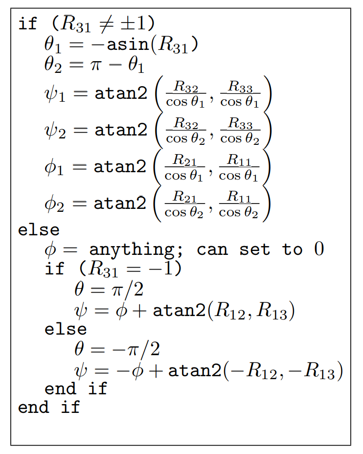
- 첫 조건문의 \(R_{31} \ne \pm 1\) 은 \(\theta \ne \pm\frac{\pi}{2}\) 을 의미합니다.
- 첫 조건문에서
else로 분기되면 \(\phi\) 는 어떤 값이 되어도 되므로 임의로 0으로 지정할 수 있습니다.
- 정리하면 임의의
Rotation행렬을Euler Angle의Roll,Pitch,Yaw로 분해할 수 있습니다. - 이 때, 특정 한 축의 회전각이 \(\pm\frac{\pi}{2}\) 인 경우가 아니라면 2개의 해를 가지게 되고 회전 각도의 범위를 고려하여 1개의 해를 선택하여 사용할 수 있습니다. 반면 한 축의 회전각이 \(\pm\frac{\pi}{2}\) 인 경우에는 무한히 많은 해를 가지게 되며
Gimbal Lock현상이 발생합니다.
python code
- 먼저 앞에서 설명한 기호를 이용하여 코드를 작성하면 다음과 같습니다.
import numpy as np

# Define the conversion function
def rotation_matrix_to_euler_angles(R):
    assert(R.shape == (3, 3))

    if R[2, 0] != 1 and R[2, 0] != -1:
        theta1 = -np.arcsin(R[2, 0])
        theta2 = np.pi - theta1
        psi1 = np.arctan2(R[2, 1] / np.cos(theta1), R[2, 2] / np.cos(theta1))
        psi2 = np.arctan2(R[2, 1] / np.cos(theta2), R[2, 2] / np.cos(theta2))
        phi1 = np.arctan2(R[1, 0] / np.cos(theta1), R[0, 0] / np.cos(theta1))
        phi2 = np.arctan2(R[1, 0] / np.cos(theta2), R[0, 0] / np.cos(theta2))
        return (psi1, theta1, phi1), (psi2, theta2, phi2)
    else:
        phi = 0  # can set to anything, it's the gimbal lock case
        if R[2, 0] == -1:
            theta = np.pi / 2
            psi = phi + np.arctan2(R[0, 1], R[0, 2])
        else:
            theta = -np.pi / 2
            psi = -phi + np.arctan2(-R[0, 1], -R[0, 2])
        return (psi, theta, phi), (None, None, None)

# Example rotation matrix
R_example = np.array([
    [0.5, -0.1464, 0.8536],
    [0.5, 0.8536, -0.1464],
    [-0.7071, 0.5, 0.5]
])


# Get the Euler angles
euler_angles_set_1, euler_angles_set_2 = rotation_matrix_to_euler_angles(R_example)

print("euler_angles_set_1:")
print(f"psi: {euler_angles_set_1[0]} radian.({euler_angles_set_1[0] * 180 / np.pi} deg).")
print(f"theta: {euler_angles_set_1[1]} radian.({euler_angles_set_1[1] * 180 / np.pi} deg).")
print(f"phi: {euler_angles_set_1[2]} radian.({euler_angles_set_1[2] * 180 / np.pi} deg).")

print("\neuler_angles_set_2:")
print(f"psi: {euler_angles_set_2[0]} radian.({euler_angles_set_2[0] * 180 / np.pi} deg).")
print(f"theta: {euler_angles_set_2[1]} radian.({euler_angles_set_2[1] * 180 / np.pi} deg).")
print(f"phi: {euler_angles_set_2[2]} radian.({euler_angles_set_2[2] * 180 / np.pi} deg).")

# euler_angles_set_1:
# psi: 0.7853981633974483 radian.(45.0 deg).
# theta: 0.7853885733974476 radian.(44.99945053347443 deg).
# phi: 0.7853981633974483 radian.(45.0 deg).

# euler_angles_set_2:
# psi: -2.356194490192345 radian.(-135.0 deg).
# theta: 2.3562040801923456 radian.(135.00054946652557 deg).
# phi: -2.356194490192345 radian.(-135.0 deg).
- 먼저 첫번째 셋의 결과는 다음과 같습니다.
psi= 0.7853981633974483 radian.(45.0 deg).theta= 0.7853885733974476 radian.(44.99945053347443 deg).phi= 0.7853981633974483 radian.(45.0 deg).
- 두번째 셋의 결과는 다음과 같습니다.
psi= -2.356194490192345 radian.(-135.0 deg).theta= 2.3562040801923456 radian.(135.00054946652557 deg).phi= -2.356194490192345 radian.(-135.0 deg).
- 일반적으로 첫번째 셋의 결과를 사용하면 됩니다.
- 다음으로 많이 사용하는
roll,pitch,yaw로 바꾸어서 표현하면 다음과 같습니다. 구현 방법 및 결과는 동일합니다.
import numpy as np

# Redefine the conversion function using roll, pitch, and yaw after the code state reset
def rotation_matrix_to_euler_angles(R):
    assert(R.shape == (3, 3))

    if R[2, 0] != 1 and R[2, 0] != -1:
        pitch1 = -np.arcsin(R[2, 0])
        pitch2 = np.pi - pitch1
        roll1 = np.arctan2(R[2, 1] / np.cos(pitch1), R[2, 2] / np.cos(pitch1))
        roll2 = np.arctan2(R[2, 1] / np.cos(pitch2), R[2, 2] / np.cos(pitch2))
        yaw1 = np.arctan2(R[1, 0] / np.cos(pitch1), R[0, 0] / np.cos(pitch1))
        yaw2 = np.arctan2(R[1, 0] / np.cos(pitch2), R[0, 0] / np.cos(pitch2))
        return (roll1, pitch1, yaw1), (roll2, pitch2, yaw2)
    else:
        yaw = 0  # can set to anything, it's the gimbal lock case
        if R[2, 0] == -1:
            pitch = np.pi / 2
            roll = yaw + np.arctan2(R[0, 1], R[0, 2])
        else:
            pitch = -np.pi / 2
            roll = -yaw + np.arctan2(-R[0, 1], -R[0, 2])
        return (roll, pitch, yaw), (None, None, None)

# Example rotation matrix
R_example = np.array([
    [0.5, -0.1464, 0.8536],
    [0.5, 0.8536, -0.1464],
    [-0.7071, 0.5, 0.5]
])


# Get the Euler angles
euler_angles_set_1, euler_angles_set_2 = rotation_matrix_to_euler_angles(R_example)

print("euler_angles_set_1:")
print(f"Roll: {euler_angles_set_1[0]} radian.({euler_angles_set_1[0] * 180 / np.pi} deg).")
print(f"Pitch: {euler_angles_set_1[1]} radian.({euler_angles_set_1[1] * 180 / np.pi} deg).")
print(f"Yaw: {euler_angles_set_1[2]} radian.({euler_angles_set_1[2] * 180 / np.pi} deg).")

print("\neuler_angles_set_2:")
print(f"Roll: {euler_angles_set_2[0]} radian.({euler_angles_set_2[0] * 180 / np.pi} deg).")
print(f"Pitch: {euler_angles_set_2[1]} radian.({euler_angles_set_2[1] * 180 / np.pi} deg).")
print(f"Yaw: {euler_angles_set_2[2]} radian.({euler_angles_set_2[2] * 180 / np.pi} deg).")
# euler_angles_set_1:
# Roll: 0.7853981633974483 radian.(45.0 deg).
# Pitch: 0.7853885733974476 radian.(44.99945053347443 deg).
# Yaw: 0.7853981633974483 radian.(45.0 deg).

# euler_angles_set_2:
# Roll: -2.356194490192345 radian.(-135.0 deg).
# Pitch: 2.3562040801923456 radian.(135.00054946652557 deg).
# Yaw: -2.356194490192345 radian.(-135.0 deg).
- 위 코드의 결과를 수식을 통해 계산한 결과와 비교해 보도록 하겠습니다.
- \[R = \begin{bmatrix} 0.5 & -0.1464 & 0.8536 \\ 0.5 & 0.8536 & -0.1464 \\ -0.7071 & 0.5 & 0.5 \end{bmatrix}\]
- \[\theta_{1} = -\sin{(-0.7071)} = \frac{\pi}{4}\]
- \[\theta_{2} = \pi - \theta_{1} = \pi - \frac{\pi}{4} = \frac{3 \pi}{4}\]
- \[\psi_{1} = \text{atan2}(\frac{0.5}{\cos{(\pi/4)}}, \frac{0.5}{\cos{(\pi/4)}}) = \frac{\pi}{4}\]
- \[\psi_{2} = \text{atan2}(\frac{0.5}{\cos{(3\pi/4)}}, \frac{0.5}{\cos{(3\pi/4)}}) = -\frac{3\pi}{4}\]
- \[\phi_{1} = \text{atan2}(\frac{0.5}{\cos{(\pi/4)}}, \frac{0.5}{\cos{(\pi/4)}}) = \frac{\pi}{4}\]
- \[\psi_{2} = \text{atan2}(\frac{0.5}{\cos{(3\pi/4)}}, \frac{0.5}{\cos{(3\pi/4)}}) = -\frac{3\pi}{4}\]
- \[(\psi_{1}(\text{Roll}), \theta_{1}(\text{Pitch}), \phi_{1}(\text{Yaw})) = (\frac{\pi}{4}, \frac{\pi}{4}, \frac{\pi}{4})\]
- \[(\psi_{2}(\text{Roll}), \theta_{2}(\text{Pitch}), \phi_{2}(\text{Yaw})) = (-\frac{3\pi}{4}, \frac{3\pi}{4}, -\frac{3\pi}{4})\]
- 만약
Gimbal Lock과 같은 상황을 고려하지 않고 간단하게Roll,Pitch,Yaw를 구하고 싶다면 다음과 같이 간단하게 사용할 수 있습니다.
def rotation_matrix_to_euler_angles(R):
    assert(R.shape == (3, 3))
    theta = -np.arcsin(R[2, 0])
    psi = np.arctan2(R[2, 1] / np.cos(theta), R[2, 2] / np.cos(theta))
    phi = np.arctan2(R[1, 0] / np.cos(theta), R[0, 0] / np.cos(theta))
    return np.array([psi, theta, phi]) # Roll, Pitch, Yaw